National Motorway Communications System Specifications(TR Series)
TR2031- Loop Detector Feeder Cable
Application and Description
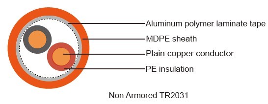
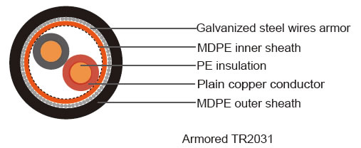
TR2031 loop detector feeder cable is a copper communications cable sheathed with medium density polyethyylene (MDPE) designed for installation in a ducted network. Armoured feeder cables are used to feed electrical current to inductive cable loops and designed for direct burial underground.
Standard
BS 6500
Cable Construction

- Conductor: Solid plain annealed copper, comply with IEC 60228 for Class 1
- Insulation: Polythene (PE), comply with IEC 60708
- Core Identification: 1 pair – red, black
2 pair – red, yellow, blue, black laid up in quad formation in order of rotation
- Screen (for Non Armoured Cable Only)): Aluminum polymer laminate tape comply with IEC
60708
- Inner Sheath (for Armoured Cable Only): Medium density polyethylene (MDPE), comply with IEC
60708
- Armor (for Armoured Cable Only): Galvanized steel wires to BS EN 10257-1
- Outer Sheath: Medium density polyethylene (MDPE), comply with IEC 60708.
- Outer Sheath Color: Orange/Black

Technical Characteristics
- Rated voltage: 600/Kft volts
- Minimum bending radius: 8 x O
- Rated temperature: +70o C
- Conductor resistance at 20°C: 1.5mm2---- 12.1ohms/km
2.5mm2---- 7.41ohms/km
- Insulation resistance: >1500 MO x km
- Loop inductance: 630uH/km(1P) 720uH/km(2P)
- Capacitance:
| unarmored | armored | |||
| 1.5 mm2 | 2.5 mm2 | 1.5 mm2 | 2.5 mm2 | |
| <75 pF/m | (1P) | pF/m | 64 pF/m (1P) | |
| 52 pF/m (2P) | 53.5 pF/m (2P) | |||
-Current rating
| Unarmored in air (30°C) | armored in ground (15oC, 1.2oC m/W) | ||
| 1.5 mm2 | 2.5 mm2 | 1.5 mm2 | 2.5 mm2 |
| 24* | 33* | 32* | 41* |
*These ratings are based on only two cores loaded simultaneously. In two pair cables where all four cores could be loaded simultaneously, the above values should be multiplied by 0.78.
Cable Parameter
| Number of Pairs |
Nominal Conductor Area |
Nominal Conductor Stranding |
Insulation Thickness |
Inner Sheath Thickness |
Nominal diameter of armour wire |
Outer Sheath Thickness |
Nominal O/D | Approx Cable Weight |
| mm2 | NO./mm | mm | mm | mm | mm | mm | Kg/km | |
| Unarmored cables | ||||||||
| 1 | 1.5 | 1/1.38 | 0.70 | - | - | 1.4 | 7.5 | 92 |
| 2 (Q) | 1.5 | 1/1.38 | 0.70 | - | - | 1.4 | 12.0 | 173 |
| 1 | 2.5 | 1/1.78 | 0.70 | - | - | 1.4 | 8.1 | 121 |
| 2 (Q) | 2.5 | 1/1.78 | 0.70 | - | - | 1.4 | 13.3 | 231 |
| Armored cables | ||||||||
| 1 | 1.5 | 1/1.38 | 0.70 | 0.7 | 0.9 | 1.4 | 10.6 | 255 |
| 2 (Q) | 1.5 | 1/1.38 | 0.70 | 0.7 | 0.9 | 1.4 | 11.5 | 327 |
| 1 | 2.5 | 1/1.78 | 0.70 | 0.7 | 0.9 | 1.4 | 11.2 | 296 |
| 2 (Q) | 2.5 | 1/1.78 | 0.70 | 0.7 | 0.9 | 1.4 | 12.3 | 395 |

